
Original Inotec Crimpflange technology
Standard assembly procedure KV0001
The standard procedure described below allows an easy and reliable assembly process for the major part of all shielded cables. Variations in cable construction or materials may require the processing following different assembly procedures. With the cable-specific crimp data definition we determine the required assembly parameters, component diameters and tool sizes for every specific application as a service for our customer.
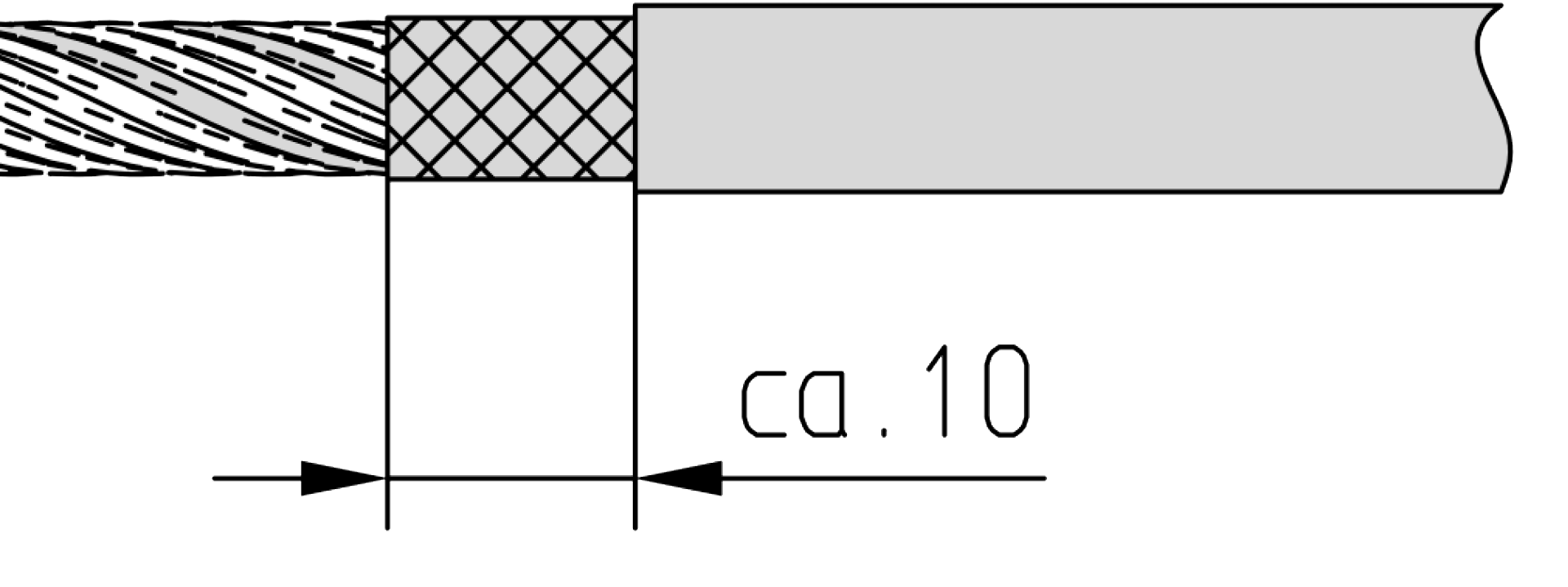
1. Dismantle the cable down to the braid and cut the braid, leaving it approx. 10 mm longer than the jacket.
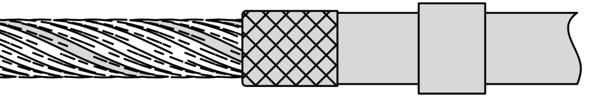
2. Fold back the braid over the cable sheath and slide the crimp ferrule on the cable.
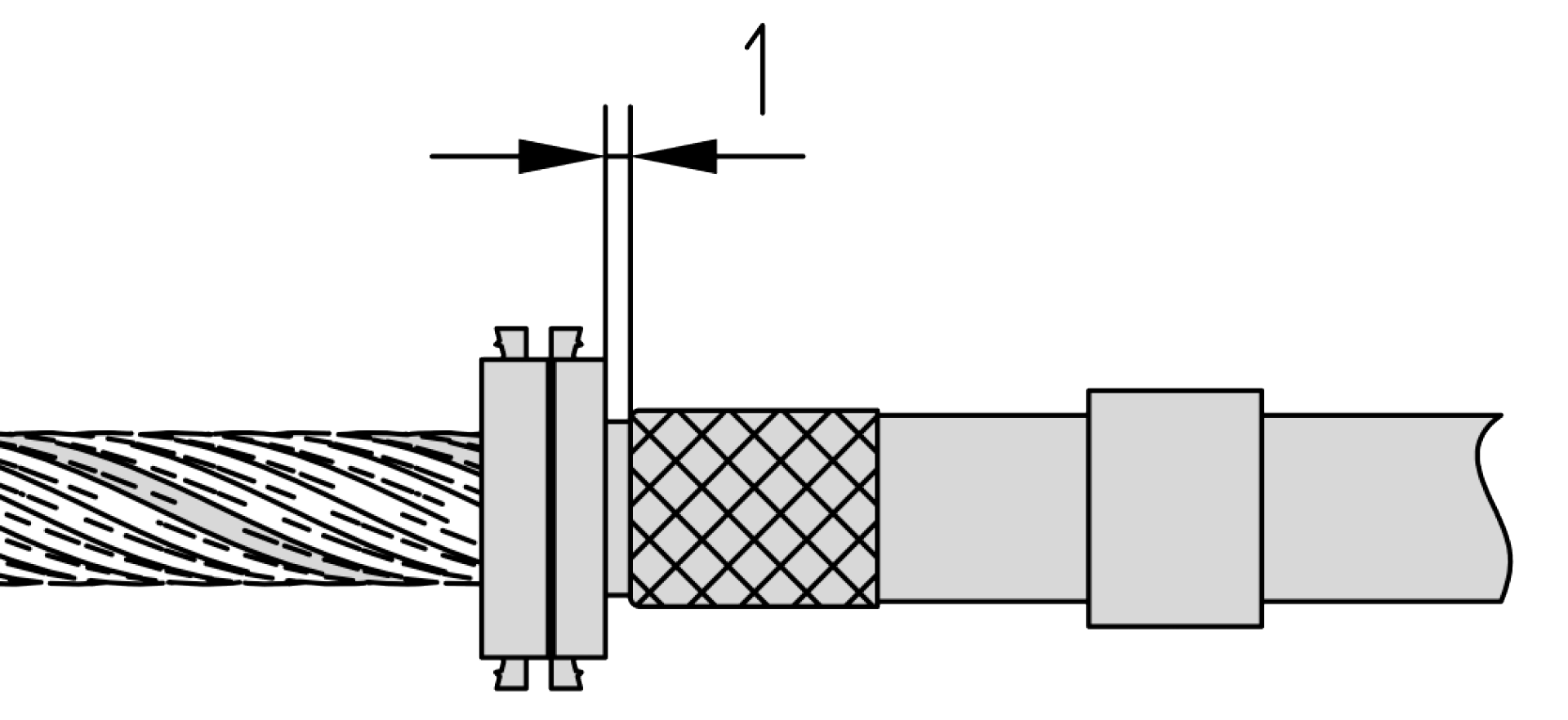
3. Slip the crimp flange over the conductors and possible intermediate layers and slide it underneath the shield mesh and the cable sheath. Enter the flange with cautious rotation while holding back the shield mesh. In this step, do not enter the flange completely but keep approx. 1 mm distance to the cable sheath in order to facilitate the cutting of the shield mesh.
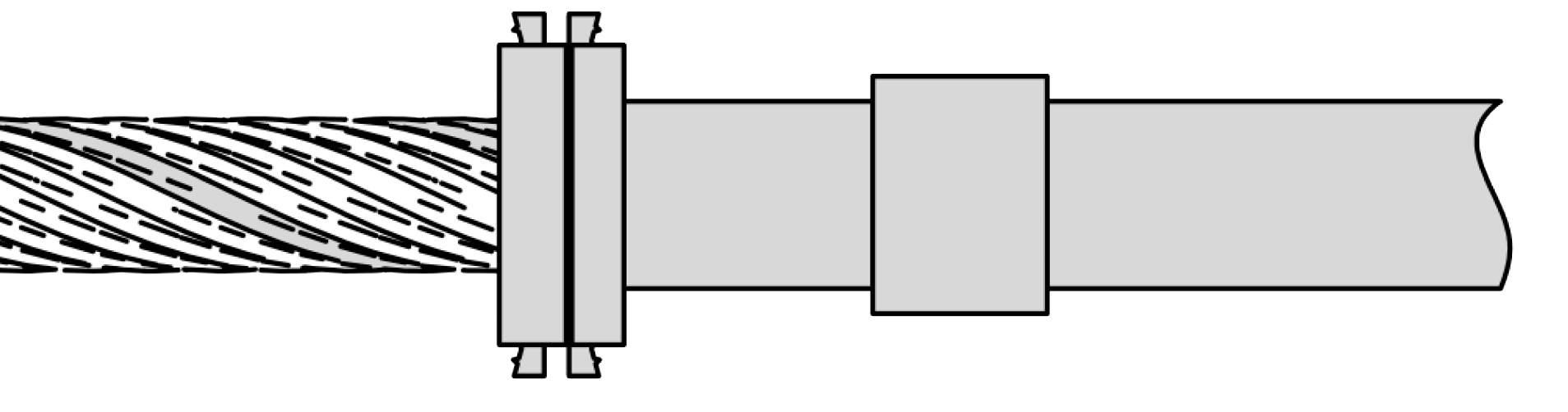
4. Cut off any overlapping braid around the flange. Only now slide the crimp flange completely underneath shield mesh and cable sheath. Please note: Our insertion tool CFE facilitates the handling of the flange in step 3 and 4.
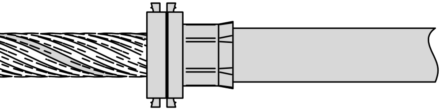
5. Slide the crimp ferrule forward until it is in contact with the flange. Keep it in position and crimp it with the indicated crimp dies. Important: During the crimping process the flange has to lay on the crimp dies. The faces of the hexagon should be parallel to the straight sides of the crimp flanges (see illustration).
The Inotec crimp data definition
A basic requirement to achieve sufficient mechanical strength and optimal cable shield contact is to match components, tools and applied assembly procedures for every specific cable assembly. Unlike comparable crimp technologies the Inotec system provides a finely graduated diameter range (0,5 mm steps) and covers a very wide range of crimp flange, ferrule and crimp die diameters.
As an exclusive customer service Inotec electronics GmbH provides a crimp data definition for every specific cable and all cable manufacturers.
Required input data and sample:
Required input data and sample:
- Cable sample (min. 0,5 m)
- Intended use (Inotec hood type)
- Cable data sheet (if available)
- Documentation of the cable sample provided.
- Definition of the most suitable and reliable assembly procedure (if standard procedure KV0001 cannot be recommended, a corresponding data sheet with detailed processing instructions is provided)
- Definition of the most appropriate components (crimp flange and ferrule)
- Definition of the appropriate crimp die type and size
- Additional recommendations or assembly instructions if required.
Example for cable specific Inotec crimp data sheets
