Original Inotec crimp flange system
Cable processing with original Inotec crimp flange technology
Exemplary illustration of the standard cable processing KV0001 with crimp flange CF100 and crimp ferrule on the basis of micrographs.
The 360° contact between the cable shield and the crimp flange is clearly visible. The cable is not deformed in cross-section, the cores remain free of mechanical stress in the crimp area. Specific properties of the cable, such as a soft or relatively thick cable jacket, can reduce the torsional strength of the hexagon crimp. In these cases, an additional embossing is added by means of a trapezoidal indent in the crimp die.
The Inotec crimp data definition
A basic requirement to achieve sufficient mechanical strength and optimal cable shield contact is to match components, tools and applied assembly procedures for every specific cable assembly. Unlike comparable crimp technologies the Inotec system provides a finely graduated diameter range (0,5 mm steps) and covers a very wide range of crimp flange, ferrule and crimp die diameters.
As an exclusive customer service Inotec electronics GmbH provides a crimp data definition for every specific cable and all cable manufacturers.
Required input data and sample:
- Cable sample (min. 0,5 m)
- Intended use (Inotec hood type)
- Cable data sheet (if available)
Based on this information, the Inotec mechanical laboratory realizes assembly tryout, traction and torque test in order to find out the optimal combination of convenient assembly, reliable cable shield contact and best possible mechanical resistance of the crimped connection. Once the crimp data definition is accomplished, the customer receives a crimp data sheet and a crimped cable sample. The customer’s data sheet contains the following relevant information.
- Documentation of the cable sample provided.
- Definition of the most suitable and reliable assembly procedure (if standard procedure KV0001 cannot be recommended, a corresponding data sheet with detailed processing instructions is provided)
- Definition of the most appropriate components (crimp flange and ferrule)
- Definition of the appropriate crimp die type and size
- Additional recommendations or assembly instructions if required.
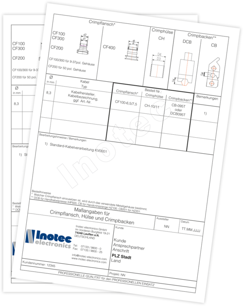
Example for cable specific Inotec crimp data sheets

Documentation of a cable-specific crimp data definition
- The headline resumes all components and types of crimp dies that can be used with Inotec crim flange technology.
- The data section shows
- diameter of the cable sample
- cable designation
- defined crimp flange size (CF-type according to customers requirements)
- crimp ferrule size (if applicable)
- corresponding cimp die size and type - In the field for additional technical information, the processing instruction to apply is indicated and additional remarks or process steps are given.
Micrographs of cable processing according to KV0001 (standard processing), without and with trapezoidal indent


Important features of correct cable processing:
- Regular and fully formed hexagonal contour
- 360° contact between shield braid and crimp flange
- No squeezing of the wires and damage to the cable sheath
